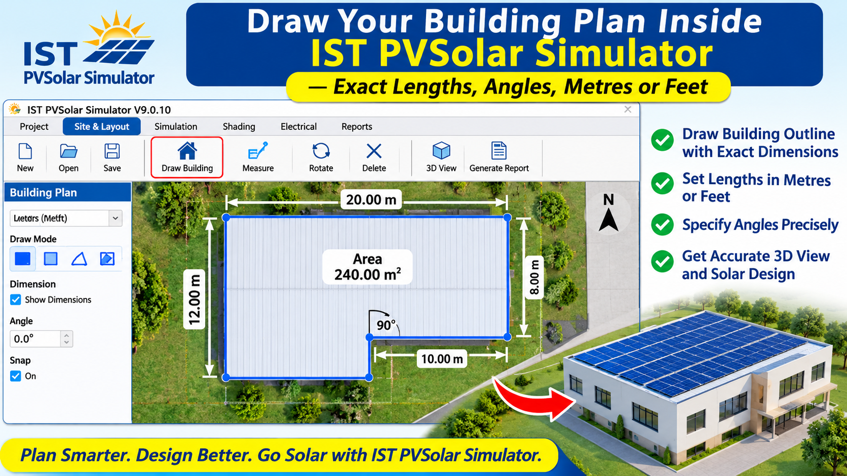
Draw Your Building Plan Inside IST PVSolar Simulator — Exact Lengths, Angles, Metres or Feet
IST PVSolar Simulator now lets you draw a building's exact outline inside 3D Shadow Analysis, in metres or feet, and turn it into a 3D building for shadow study in one click. No drone image, satellite map or plan file is needed.
Many rooftop projects start with nothing but a site visit sketch: a few wall lengths noted on paper and a rough idea of which way the building faces. Until now, getting that building into a shadow study meant finding an image to trace over. The new Draw Building Plan tool, under Find Loc. in 3D Shadow Analysis, removes that step. You type the wall lengths, set each wall's direction from north, and the simulator builds the roof and the 3D model from your exact measurements.
What's new at a glance
- A drawing board inside 3D Shadow Analysis, opened from the Find Loc. bar, with north always at the top.
- Walls by length and direction: type a length, then point the wall the right way. The angle from north and the corner angle to the previous wall show live as you place it.
- CAD-style tools: line, curve, rectangle, select and edit, trim, erase, measure, close shape, undo and redo.
- Metres or feet: pick a unit and everything converts automatically. Feet can be typed as
60.5or60'6". - One-click Apply: the outline becomes the 2D map at an exact scale, the roof outline and a 3D building, ready for shadow analysis.
- Saved with the project: reopen the drawing at any time, change it and apply again.
How it works: draw a wall the way you measure it
Every wall is placed the way an engineer measures on site: a length, then a direction. Angles are bearings from north, clockwise, so 0° is north, 90° east, 180° south and 270° west.
- In 3D Shadow Analysis, open Find Loc. and click Draw Building Plan.
- Choose the Line tool and click the first corner of the building.
- Type the wall's length and press Enter.
- Move the mouse towards the direction of the wall. The wall keeps its length and swings round as you move, showing its angle from north and the corner angle to the previous wall.
- Click to place it, or type the exact angle and press Enter.
- The next wall starts from that corner automatically. Repeat until you are back at the first corner, or press Close.
While you draw, the angle snaps to half degrees, to north, east, south and west, and to square corners. Holding Shift gives 15° steps. Once the outline is closed, a panel confirms it and shows the number of corners, the area and the perimeter. Any open wall ends are marked in red, so gaps are easy to find.
Example: an L-shaped building of 20 m × 12 m with a 8 m × 6 m corner cut out takes six walls: 20 m at 90°, 12 m at 180°, 8 m at 270°, 6 m at 0°, 12 m at 270°, then Close. The tool reports a closed outline of 168 m², exactly as measured.
Metres or feet, converted automatically
A Unit choice at the top of the drawing board switches between Metre (m) and Feet (ft). Every length you type and see follows it: wall lengths, radius and depth, the grid, building height, free ground around the building, area (m² or ft²), perimeter and the scale bar. The system converts automatically, using 1 ft = 0.3048 m.
- Feet are shown the way plans are written, for example 60′-6″, to the nearest half inch.
- Type feet either way:
60.5,60'6",60' 6or60'-6½"all work. - Switching never changes the drawing. Values already typed are converted, and the grid moves between 0.5 m and 1 ft.
- The choice is remembered and saved with the project.
A 60′-6″ × 40′ building drawn in feet reports 2,420 ft² and becomes exactly 224.8 m² on the map. The 3D model and the shadow results are identical whichever unit you draw in.
From drawing to 3D shadow analysis in one click
Pressing Apply turns the closed outline into everything the shadow study needs:
- A 2D map at an exact scale, with north up and the free ground you choose around the building for drawing its surroundings.
- The roof outline, taken from your exact corners rather than traced from an image.
- A 3D building at the height you entered. The 3D Preview opens straight away.
- The module azimuth, set from the building's sun-facing side so arrays run parallel to the walls, as with an uploaded plan.
From there, the usual workflow continues. Add parapets and rooftop objects, mark the surrounding buildings, trees and poles with their heights, lay out the arrays, and run the full 3D shadow analysis: near and far shading, shadow-free row pitch and estimated yield loss. If the building changes, reopen Draw Building Plan, adjust the walls and apply again.
Who it helps
- EPC companies and installers can turn a site-visit sketch into a shadow study the same day, before any drone flight.
- Solar consultants can model buildings where imagery is old, blurred or hidden by trees, using measured dimensions instead.
- Designers working in feet can draw in the unit their drawings and clients use, without converting by hand.
- Students and trainees learn bearings, building orientation and shading with a tool that shows every angle as they draw.
The result is a faster start on every rooftop project, and a shadow study built on the building's true size and orientation.
Try it today
Draw Building Plan is available now in IST PVSolar Simulator for every user. Open your dashboard, start a project, and go to 3D Shadow Analysis → Find Loc. → Draw Building Plan. The Help page explains every tool, and our video tutorials walk through the full shadow-analysis workflow.