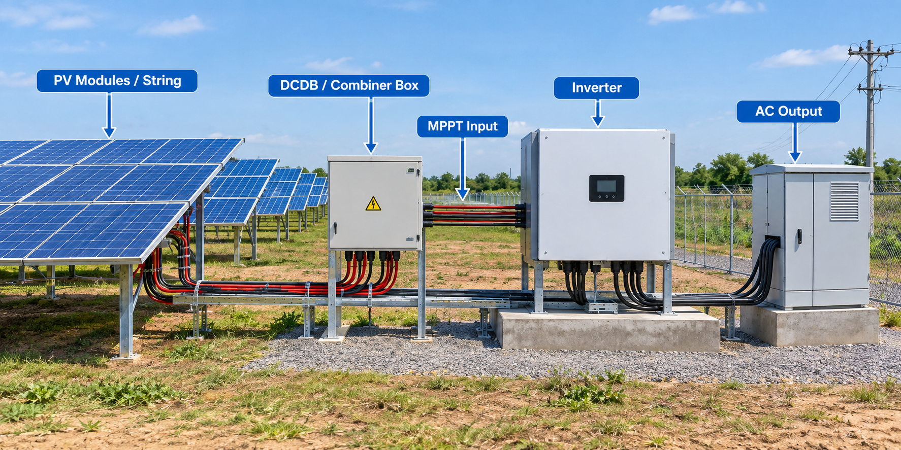
Array Connection & Electrical Diagram: From PV Array to Inverter — A Design & Calculation Guide
Every solar PV plant, whether a 5 kW rooftop system or a 50 MW utility-scale plant, follows the same fundamental electrical hierarchy on the DC side: modules → strings → DCDB (combiner) → MPPT → Inverter. Getting this chain right — both the wiring topology and the underlying calculations — is what separates a system that performs reliably for 25 years from one plagued by hotspots, nuisance trips, or voltage-drop losses. This post walks through each stage of that connection, the electrical rules governing it, and the formulas used to size cables and protection devices correctly.
1. The Basic Hierarchy
Module → Module → ... → Module   (in series = 1 STRING)
   String 1 ─┐
   String 2 ─┼──► DCDB / Combiner Box ──► MPPT input ──► Inverter ──► AC Output
   String n ─┘
- Module: the individual PV panel, rated at STC (1000 W/m², 25°C) with Voc, Vmp, Isc, Imp on its nameplate.
- String: a series chain of modules. Voltages add; current stays the same as one module.
- DCDB (DC Distribution Board), also called a combiner box or AJB (Array Junction Box): where multiple strings are paralleled. Currents add; voltage stays the same as one string.
- MPPT (Maximum Power Point Tracker): an independent input channel inside the inverter that hunts for the optimum operating point of the strings connected to it.
- Inverter: converts the combined DC power into grid-synchronized AC.
2. Array to DCDB: String Sizing and Combiner Design
Why strings are sized the way they are
The number of modules per string is bounded by the inverter's MPPT voltage window and maximum DC input voltage, and this must be checked at temperature extremes, not just STC:
- Maximum modules/string — limited by cold-weather Voc (voltage rises as temperature falls):
- Minimum modules/string — limited by hot-weather Vmp (voltage falls as temperature rises):
  Voc_cold = Voc_STC × [1 + (α_Voc/100) × (T_min − 25)]
N_max = floor(V_inverter_max_DC / Voc_cold) Vmp_hot = Vmp_STC × [1 + (α_Pmax/100) × (T_max − 25)]
N_min = ceil(V_MPPT_min / Vmp_hot)Here T_min is the record low ambient temperature for the site (used for the worst-case cold Voc check) and T_max is the design summer cell temperature (used for the worst-case hot Vmp check). A string sized between N_min and N_max, with some margin (commonly targeting ~90–95% of N_max) balances safety margin against harvesting the most energy per string.
DCDB / combiner box design
Each string enters the DCDB through its own fuse (or breaker) and typically a blocking diode is not needed in modern gPV-fused designs. Key calculations:
- String fuse rating:
I_fuse ≥ 1.25 × Isc_modulerounded up to the nearest standard gPV rating (e.g., 10A, 15A, 16A), and must stay below the module's maximum series fuse rating (usually 2.4 × Isc) per the datasheet.
- DCDB output (combined) current — the current the DCDB busbar and its outgoing feeder cable must carry:
I_DCDB = N_strings × Isc_module × 1.25- Surge Protection (SPD): a Type 2 DC SPD is fitted at the DCDB, rated for at least 1.2 × the string's cold Voc, with In ≥ 5 kA per IEC 61643-31.
- Cable from module string to DCDB: sized for
1.25 × Iscampacity, then checked against voltage drop (see §5).
3. DCDB to MPPT/Inverter: The Feeder Run
The DCDB's combined output feeds a single, larger cable — the feeder — that runs to one MPPT input on the inverter. This cable must be sized for the full combined current:
Feeder cable rating ≥ I_DCDB = N_strings × Isc_module × 1.25Because this is the highest-current DC segment before the inverter, it's usually the largest-gauge DC cable in the array (commonly 10–50 mm² depending on plant size), and the segment where voltage drop matters most since even a small percentage drop here represents real lost energy across the whole day.
How many strings can go to one MPPT? This is fixed by the inverter datasheet's "Max input current per MPPT" and "Strings per MPPT" ratings:
Array current per MPPT = Imp_module × Strings_per_MPPT ≤ I_MPPT_max (datasheet)If a design calls for more strings than one MPPT can handle, they must be split across multiple MPPTs, each independently tracked — which is also the correct approach whenever strings face different tilt, azimuth, or partial-shading conditions, since mixing mismatched strings on one MPPT drags the whole group's operating point down to the weakest string.
4. MPPT to Inverter: Matching the Whole Array
At the inverter level, the checks scale up from a single string to the whole array feeding that inverter:
- Total DC current into the inverter:
I_total = Imp_module × Strings_per_MPPT × MPPT_used × (this doesn't exceed) I_dc_max (inverter)- Array-to-inverter (ILR / DC:AC ratio) — the ratio of installed DC capacity to the inverter's rated AC output:
ILR = P_DC (kWp) / P_AC (kW)A typical ILR of 1.1–1.25 is common practice: slightly oversizing the DC array relative to the inverter captures more energy during low-irradiance periods (mornings, evenings, cloudy days) at the cost of some clipping loss during peak sun, when array output would otherwise exceed the inverter's AC rating. The optimum ILR is a site-specific trade-off between the local irradiance profile and clipping losses.
- MCCB / breaker at the inverter's AC or DC input, sized per:
I_breaker ≥ 1.25 × I_full_load
rounded to the next standard frame size.
5. Voltage Drop: The Calculation That Ties It All Together
Every cable segment in this chain — string-to-DCDB, DCDB-to-inverter, and inverter-to-grid — loses some voltage (and therefore energy) to resistance. The standard formula:
DC segments (2-wire):
Vd = 2 × L × I × ρ / AAC three-phase segments:
Vd = √3 × L × I × ρ / AWhere:
L= one-way cable length (m)I= design current (A)ρ= resistivity of copper (~0.0225 Ω·mm²/m at typical operating temperature)A= cable cross-sectional area (mm²)
The resulting voltage drop is then expressed as a percentage of the reference voltage (Vmp of the string for DC segments, or system AC voltage for AC segments) and checked against an allowable limit. Industry practice typically scales the allowable DC drop with plant size (e.g., ~1.5% for small rooftop systems down to ~0.8% for multi-MW plants) and applies segment-specific AC limits depending on the topology (inverter-to-ACDB, LV busbar-to-transformer, etc.), per IEC 60364-5-52 guidance. If a proposed cable size exceeds the limit, the next larger standard size is selected.
6. Putting It Together: A Worked Example
Suppose a 500 kWp plant uses modules rated Voc = 49.5V, Vmp = 41.2V, Isc = 11.5A, Imp = 10.9A, strung 24 modules/string (giving ~990V Vmp per string — safely inside a 1000V window), 3 strings per MPPT, 10 MPPTs per inverter, and 2 inverters:
- Fuse per string: 1.25 × 11.5 = 14.4A → next standard rating, 15A gPV fuse.
- DCDB output current (per DCDB feeding one inverter's full array): with 30 strings combined per inverter,
30 × 11.5 × 1.25 ≈ 431Acombined feeder demand — in practice this is split across the 10 separate MPPT feeders (3 strings each), so each individual MPPT feeder carries3 × 11.5 × 1.25 ≈ 43A. - Array current per MPPT:
3 × 10.9 = 32.7A, checked against the inverter's rated max input current per MPPT. - Cable sizing: each MPPT feeder cable sized for ≥43A ampacity, then checked for voltage drop over its actual run length; if the drop exceeds the site's allowable %, step up one cable size.
Key Takeaways
- Size strings first against cold Voc and hot Vmp limits — this single decision constrains everything downstream.
- DCDB fuses and feeders scale with the number of strings combined — always use
1.25 × Iscas the safety multiplier for protection devices. - Respect the inverter's per-MPPT current and string-count limits — never combine mismatched strings (different orientation/shading) on the same MPPT.
- Check voltage drop on every segment, not just current-carrying capacity — a cable can be "big enough" for current and still cause unacceptable energy loss if it's too long and too thin.
- ILR is a deliberate design choice, not an error — moderate oversizing (DC:AC > 1.0) is standard practice, and clipping loss should be evaluated against the energy gained in low-light hours.
Getting the array-to-inverter wiring diagram right isn't just a drafting exercise — it's where a plant's lifetime energy yield, safety margins, and maintainability are actually decided.