One Project, Every Roof: Simulating Mixed Pitch, Flat, and Ground-Mount Arrays Together in IST PVSolar Simulator 9.0.10
Real rooftops are rarely one clean plane. A typical commercial or residential site might have a south-facing pitched section, a flat parapet-walled section next to it, a small east-facing dormer that catches morning sun, and — if there's spare land — a ground-mount array bolted on for good measure. Most solar design tools force a compromise here: pick one tilt, one azimuth, one mounting type for the whole project, and treat everything else as a rough correction factor.
IST PVSolar Simulator 9.0.10 doesn't make that compromise. It can trace, place panels on, and — critically — correctly simulate the energy output of any number of pitched roof faces, flat roof areas, and ground-mount parcels within a single project, and it does this with real per-orientation physics, not a single blended average.
Step 1: Trace every roof and area you have — mixed freely
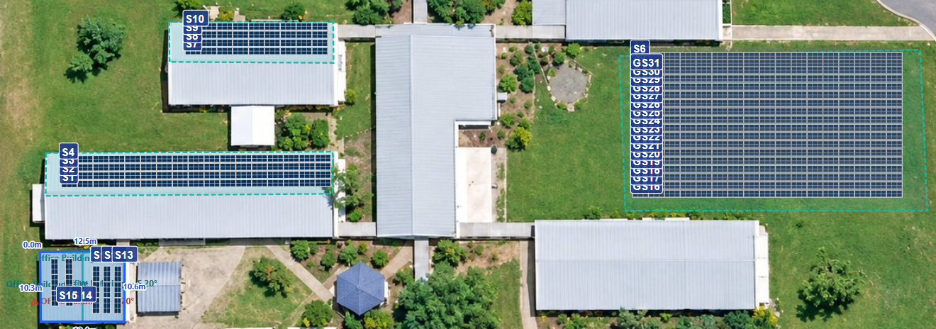
Inside the 3D Shadow Analysis tool, "Roof Type" (for pitch/flat roof faces) and "Ground Area" (for ground-mount parcels) are both always available on the same image, regardless of which Project Type was originally selected. The tooltip on that setting spells it out directly: it "no longer restricts which areas you can add... so one project can freely mix any number of each."
In practice that means a single traced site image can contain:
- One or more flat roof faces
- One or more pitched roof faces, each with its own independent azimuth and pitch angle
- One or more ground-mount parcels, complete with their own setback-from-boundary rules
For a pitched roof, you don't have to trace each face by hand either — the Auto (Full Roof) tool takes a single traced outline and one pitch angle, and automatically generates a complete hip roof: every face gets its own correctly-computed slope azimuth, with hips and valleys forming naturally where faces meet. In the Northern Hemisphere, faces that would be genuinely poor performers (north/northeast/northwest-facing pitches) are automatically skipped during panel auto-fill, with a clear note explaining why — the same hemisphere-aware logic applies in reverse south of the equator.
Panels remember exactly which face and mount they belong to
Every single panel placed in the layout — whether by Auto Fit, manual placement, or copy/paste — carries a reference back to the specific roof face or ground area it sits on. That face record, in turn, stores its own flat or pitch, azimuth, pitch angle, and mount type roof or ground. Nothing gets flattened into a single "the roof" abstraction — the geometry stays panel-accurate all the way through.
The engine automatically discovers and simulates each distinct orientation
This is the part that separates a real multi-roof simulation from a rough approximation. When the simulation runs, it doesn't just average all your panels' tilts and azimuths into one fictional "representative" plane. Instead, it buckets every panel by its exact (tilt, azimuth, mount) combination — so a 20° south-facing pitch face, a 10° flat roof array, and a 15° ground-mount block each become their own distinct group, weighted by how many panels sit in each one.
Each group is then run independently — its own solar-position projection, its own transposition, its own IAM, its own shading, its own thermal model — before being combined back into one project-level result. That last point matters more than it sounds: ground-mount and rooftop arrays get genuinely different thermal coefficients (ground-mount racking is assigned its own, more heavily ventilated thermal loss constants, distinct from whatever rooftop mounting type was configured), so a mixed rooftop-plus-ground-mount project doesn't just get one compromise cell-temperature model applied everywhere — each mounting type is modeled with the coefficients that actually apply to it.
Combining the groups — nothing double-counted
Once every orientation group has its own full year of hourly results, merges them with the correct arithmetic for each kind of quantity:
- Extensive quantities (actual energy — kWh generated, kWh clipped) are summed across groups, because energy from a south pitch and energy from a ground-mount block both count toward the same project total.
- Intensive quantities (POA irradiance, cell temperature, every individual loss percentage — thermal, IAM, spectral, horizon shading, MPPT-window, transformer losses, and more) are weighted by each group's share of total DC capacity, so a small east-facing dormer full of shading losses doesn't distort the project-wide loss table the same way a same-sized main array would.
- The resulting Performance Ratio, Specific Yield, P50–P95 probability bands and CO₂ savings are all computed from these correctly-combined totals — one coherent, bankable set of numbers for the whole mixed-orientation project, not a set of separate reports the designer has to add up by hand.
The output even preserves the per-group detail for transparency: sub array groups breakdown reports each orientation group's own tilt, azimuth, mount type, DC capacity share, annual AC energy, and Performance Ratio — so a reviewer can see exactly how much the ground-mount block contributed versus the pitched roof, without losing the single unified project-level headline numbers.
The 3D view renders it all together, correctly elevated
The 3D Preview doesn't just accept this mixed geometry — it visually distinguishes it. Rooftop faces and their panels are grouped and lifted to sit on top of the building mass; ground-mount areas and their panels are grouped separately and sit directly on the ground plane. Sun-path shadows, string labels and the shading calculation all run correctly across both groups simultaneously in the same scene.
Why this matters
Most tools either force a single tilt/azimuth for an entire project, or require running separate simulations per roof section and manually reconciling the results — a process that's tedious and, worse, easy to get subtly wrong. IST PVSolar Simulator's orientation-group architecture does the reconciliation correctly by construction: every panel is simulated at its own real geometry, every mounting type gets its own physically appropriate thermal treatment, and the combination math respects the difference between quantities that should sum and quantities that should be weighted — so a genuinely mixed pitched-roof, flat-roof, and ground-mount project comes out of one simulation run with one bankable, internally consistent set of results.